youtube-transcript.ai

SA04: Truss Analysis: Method of Joints

Watch with subtitles, summary & AI chat
Add the free Subkun extension — works directly on YouTube.
  • Watch
  • Subtitles
  • Summary
  • Ask AI
Try free →

This video explains how to analyze statically determinant trusses using the method of joints. It defines a truss as a structure of slender members connected by frictionless pins, where loads are applied only at the joints. The analysis involves ensuring the number of unknown forces (member forces and support reactions) equals the number of equilibrium equations available (twice the number of joints).

Full Transcript

https://www.youtube.com/watch?v=Evsjp0zKeGw
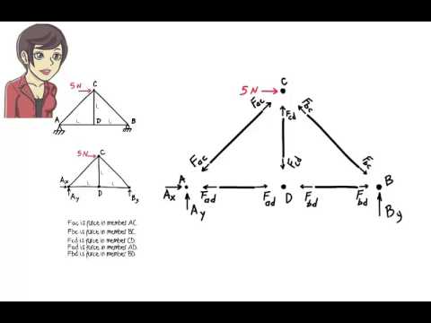
[00:00] in this session I am going to discuss.
[00:03] in this session I am going to discuss the analysis of statically determinant trusses.
[00:09] this lecture addresses two trusses.
[00:12] this lecture addresses two questions.
[00:14] what is a statically determinant trust and how to analyze it.
[00:19] a trust structure is an interconnected network of Slender members each capable of carrying an axial Force only.
[00:22] interconnected network of Slender members each capable of carrying an axial Force only.
[00:24] members each capable of carrying an axial Force only.
[00:27] axial Force only.
[00:31] the force is either compressive or tensile.
[00:35] theoretically speaking no sheer force or bending moment is present in trust members.
[00:38] force or bending moment is present in trust members.
[00:41] trust members.
[00:43] here are a few trust configurations usually seen in roofs and bridges.
[00:46] here are a few trust configurations usually seen in roofs and bridges.
[00:50] how truss Warren truss Pratt truss.
[00:55] truss.
[00:58] generally we assume trust members.
[01:01] krus generally we assume trust members are connected to each other using
[01:03] are connected to each other using frictionless
[01:05] frictionless pins this means if we have two trust
[01:08] pins this means if we have two trust members that are joined together one has
[01:11] members that are joined together one has the freedom to rotate relative to the
[01:15] the freedom to rotate relative to the other in other words trust joints cannot
[01:19] other in other words trust joints cannot resist any bending
[01:21] resist any bending moment since neither the joints nor the
[01:24] moment since neither the joints nor the members of a trust are designed to carry
[01:27] members of a trust are designed to carry any bending moment applied loads need
[01:29] any bending moment applied loads need need to be placed at the joints
[01:32] need to be placed at the joints only no load should be applied directly
[01:35] only no load should be applied directly to the trust member
[01:38] to the trust member itself here is a simple trust structure
[01:41] itself here is a simple trust structure with five members the frictionless
[01:44] with five members the frictionless joints of the trust are labeled a b c
[01:50] joints of the trust are labeled a b c and
[01:51] and d the trust is subjected to a horizontal
[01:54] d the trust is subjected to a horizontal force of five Newtons at joint
[01:57] force of five Newtons at joint C the entire structure rests on a pin
[02:01] C the entire structure rests on a pin and a
[02:03] and a roller a truss is said to be statically.
[02:07] roller a truss is said to be statically determinant if its member forces can be calculated solely using the equilibrium.
[02:10] determinant if its member forces can be calculated solely using the equilibrium equations algebraically speaking if the number of unknown forces equals to the.
[02:15] calculated solely using the equilibrium equations algebraically speaking if the number of unknown forces equals to the number of equilibrium equations then the.
[02:18] equations algebraically speaking if the number of unknown forces equals to the number of equilibrium equations then the truss is said to be statically.
[02:21] number of unknown forces equals to the number of equilibrium equations then the truss is said to be statically determinant so how many equilibrium.
[02:24] number of equilibrium equations then the truss is said to be statically determinant so how many equilibrium equations can be written for a trust.
[02:27] truss is said to be statically determinant so how many equilibrium equations can be written for a trust structure the total number of.
[02:30] determinant so how many equilibrium equations can be written for a trust structure the total number of equilibrium equations equals two times.
[02:34] equations can be written for a trust structure the total number of equilibrium equations equals two times the number of joints in the structure so.
[02:37] structure the total number of equilibrium equations equals two times the number of joints in the structure so if the truss has four joints we can.
[02:40] equilibrium equations equals two times the number of joints in the structure so if the truss has four joints we can write eight equilibrium equations for.
[02:43] the number of joints in the structure so if the truss has four joints we can write eight equilibrium equations for it Y 2 times the number of joints I am.
[02:46] if the truss has four joints we can write eight equilibrium equations for it Y 2 times the number of joints I am going to answer this question in a.
[02:49] write eight equilibrium equations for it Y 2 times the number of joints I am going to answer this question in a minute for now let's just accept it as a.
[02:54] it Y 2 times the number of joints I am going to answer this question in a minute for now let's just accept it as a fact.
[02:55] going to answer this question in a minute for now let's just accept it as a fact but what about the number of unknown.
[02:59] minute for now let's just accept it as a fact but what about the number of unknown forces the total number of unknown.
[03:00] fact but what about the number of unknown forces the total number of unknown.
[03:03] but what about the number of unknown forces the total number of unknown.
[03:06] forces the total number of unknown forces in a trust equals to the number
[03:09] forces in a trust equals to the number of its members plus the number of its
[03:11] of its members plus the number of its support
[03:13] support reactions here the truss has five
[03:16] reactions here the truss has five members each member carries an axial
[03:19] members each member carries an axial Force which needs to be determined so
[03:23] Force which needs to be determined so there are five unknown member
[03:26] there are five unknown member forces further since the structure rests
[03:29] forces further since the structure rests on a pin and a roller there are three
[03:32] on a pin and a roller there are three unknown
[03:33] unknown reactions the pin provides two reactions
[03:37] reactions the pin provides two reactions and the roller has one
[03:40] and the roller has one reaction therefore the total number of
[03:42] reaction therefore the total number of unknowns is 5 + 3 or
[03:47] unknowns is 5 + 3 or eight in this case since the number of
[03:50] eight in this case since the number of unknowns equals to the number of
[03:53] unknowns equals to the number of equations the truss is said to be
[03:55] equations the truss is said to be statically
[03:57] statically determinant how do we analyze such a
[03:59] determinant how do we analyze such a truss
[04:00] truss how do we calculate the axial force in
[04:03] how do we calculate the axial force in each
[04:04] each member there are several truss analysis
[04:07] member there are several truss analysis techniques here we are going to explain and illustrate a technique called the method of joints.
[04:13] this technique is a direct application of the principle of static equilibrium.
[04:20] according to the principle if a structure is in equilibrium then not only the equilibrium equations must be satisfied for the structure as a whole but they also must be satisfied for any of its parts.
[04:35] for example if conceptually we cut a beam into three segments with the correct internal forces shown at the cut points then the equilibrium equations must be satisfied for each segment if the entire structure is to remain in equilibrium.
[04:56] we can apply this principle in order to analyze statically determinant trusses.
[05:02] here is our simple truss let's draw the free body diagram.
[05:08] truss let's draw the free body diagram of the entire.
[05:10] of the entire structure keep in mind that each truss.
[05:13] structure keep in mind that each truss member carries an axial Force only let's.
[05:17] member carries an axial Force only let's refer to the axial force in member AC as.
[05:21] refer to the axial force in member AC as F.
[05:23] F AC similarly let's call the force in.
[05:26] AC similarly let's call the force in member BC FBC.
[05:30] member BC FBC we denote the force in each of the.
[05:32] we denote the force in each of the remaining members in a similar.
[05:36] remaining members in a similar manner now let's conceptually separate.
[05:39] manner now let's conceptually separate the members from the.
[05:44] joints that is we divide the entire.
[05:47] joints that is we divide the entire structure into nine segments there are.
[05:50] structure into nine segments there are five member segments and four joint.
[05:53] five member segments and four joint segments let's look at the segment.
[05:56] segments let's look at the segment containing member.
[05:58] containing member AC we know know the member carries an.
[06:01] AC we know know the member carries an axial Force but we don't know the.
[06:03] axial Force but we don't know the magnitude of the force we also don't.
[06:07] magnitude of the force we also don't know if the force is compressive or.
[06:11] know if the force is compressive or tensile since I want to draw the free body diagram for the segment I need to assume a direction for the force I am going to assume the force is tensile so the free body diagram for the segment looks like this the only Force present in the diagram is the unknown tensile axial force in the member labeled faac I am going to draw the free body diagram for the other member segments in a similar manner each member is assumed to carry an unknown Force the member is assumed to be in ttention now let's draw the free body diagram for the joint segments let's examine joint a first it
[07:11] Segments let's examine joint A first it connects members A and A.
[07:14] Connects members A and A D since member AC is attached to the.
[07:18] D since member AC is attached to the Joint the axial force in the member also.
[07:22] Joint the axial force in the member also acts on the joint we show this by.
[07:25] Acts on the joint we show this by placing F A on the joint note that the.
[07:30] Placing F A on the joint note that the direction of f a at the joint is.
[07:34] Direction of f a at the joint is opposite to the direction of the same.
[07:36] Opposite to the direction of the same Force shown on the member this is the.
[07:39] Force shown on the member this is the case because the two forces must cancel.
[07:42] Case because the two forces must cancel each other out that is if we reconnect.
[07:46] Each other out that is if we reconnect member AC to Joint a the sum of the.
[07:50] Member AC to Joint a the sum of the internal forces must vanish obviously.
[07:54] Internal forces must vanish obviously this happens only when the two forces.
[07:56] This happens only when the two forces are kept in the opposite directions so.
[07:59] Are kept in the opposite directions so that they cancel each other out there is.
[08:03] That they cancel each other out there is one more member force acting on the.
[08:05] One more member force acting on the joint the force in member a d again we.
[08:10] Joint the force in member a d again we place this Force at joint a in a.
[08:13] place this Force at joint a in a direction opposite to how the force is
[08:16] direction opposite to how the force is acting on member a d this completes the
[08:19] acting on member a d this completes the free body diagram of joint a at joint B
[08:24] free body diagram of joint a at joint B there are two member
[08:26] there are two member forces the force in member BC
[08:30] forces the force in member BC and the force in member b d joint C has
[08:34] and the force in member b d joint C has three member forces acting on it the
[08:37] three member forces acting on it the force in member AC the force in member
[08:41] force in member AC the force in member BC and the force in member
[08:45] BC and the force in member CD at joint D there are three member
[08:49] CD at joint D there are three member forces f a d
[08:53] forces f a d fbd and f CD now we have the complete
[08:58] fbd and f CD now we have the complete free body diagram for each segment as I
[09:02] free body diagram for each segment as I mentioned before for the entire trust to
[09:05] mentioned before for the entire trust to be in equilibrium each segment must be
[09:08] be in equilibrium each segment must be in equilibrium we can easily see that
[09:12] in equilibrium we can easily see that the equilibrium equations are satisfied
[09:14] the equilibrium equations are satisfied for each member segment the two Force
[09:18] for each member segment the two Force vectors shown in each segment cancel
[09:21] vectors shown in each segment cancel each other that is there's sum equals
[09:25] each other that is there's sum equals zero and since there is no bending
[09:28] zero and since there is no bending moment or sheer force acting on the free
[09:31] moment or sheer force acting on the free body diagram the moment equilibrium
[09:34] body diagram the moment equilibrium equation is automatically
[09:37] equation is automatically satisfied so now let's turn our
[09:40] satisfied so now let's turn our attention to the Joint segments when we
[09:43] attention to the Joint segments when we say each joint has to be in equilibrium
[09:47] say each joint has to be in equilibrium we are saying at each joint sum of the
[09:51] we are saying at each joint sum of the forces in the X direction must be
[09:55] forces in the X direction must be zero sum of the forces in the y
[09:58] zero sum of the forces in the y direction must be
[10:01] direction must be zero and some of the moments about the
[10:04] zero and some of the moments about the joint must be
[10:06] joint must be zero note that the moment equation is
[10:10] zero note that the moment equation is automatically satisfied since all the
[10:13] automatically satisfied since all the Joint Forces pass through the joint so
[10:17] Joint Forces pass through the joint so we only need to show that the other two.
[10:19] We only need to show that the other two equations are satisfied let's see how this works for joint a using the geometry of the truss we can calculate angle Alpha it is 45°.
[10:35] Then we can write sum of the forces in the X Direction equals ax plus f a d plus F A cine 45 = 0 and sum of the forces in the y direction equals a y plus f a sin 45 = 0.
[11:08] Note that we have four unknown forces but only two equations.
[11:11] Here it is not possible to find these unknowns yet let's number these.
[11:18] unknowns yet let's number these equations one and two we need to repeat equations one and two.
[11:22] we need to repeat this formulation for the other joints as this formulation for the other joints as well for joint B angle gamma can be easily calculated from the truss.
[11:24] for joint B angle gamma can be easily calculated from the truss.
[11:29] geometry the angle is.
[11:33] geometry the angle is 45°.
[11:36] the two Force equilibrium equations for this joint are.
[11:40] the two Force equilibrium equations for this joint are.
[11:43] sum of the forces in the X Direction equals netive.
[11:47] sum of the forces in the X Direction equals netive fbd minus F.
[11:50] fbd minus F BC cine 45 = 0.
[11:54] BC cine 45 = 0.
[11:58] sum of the forces in the y direction equals b y plus.
[12:01] sum of the forces in the y direction equals b y plus FBC sin 45 = 0.
[12:06] FBC sin 45 = 0.
[12:11] Let's number these equations 3 and four for joint C we have.
[12:17] equations 3 and four for joint C we have sum of the forces in the X Direction.
[12:20] sum of the forces in the X Direction equals F BC sin 45 minus f a sin 45+ + 5
[12:29] equals F BC sin 45 minus f a sin 45+ + 5 = 0 and sum of the forces in the y
[12:34] = 0 and sum of the forces in the y direction equals
[12:37] direction equals F cine 45 minus
[12:43] F cine 45 minus FBC cine 45 minus F CD equal Z these
[12:50] FBC cine 45 minus F CD equal Z these equations are labeled five and six
[12:53] equations are labeled five and six finally for joint D we have sum of the
[12:57] finally for joint D we have sum of the forces in the ex Direction equal F BD
[13:03] forces in the ex Direction equal F BD minus f a d = 0 sum of the forces in the
[13:10] minus f a d = 0 sum of the forces in the y direction equals F CD equal 0 these
[13:16] y direction equals F CD equal 0 these equations are numbered seven and eight
[13:19] equations are numbered seven and eight so we have eight equations and eight
[13:23] so we have eight equations and eight unknowns we formulated two equations per unknowns.
[13:26] we formulated two equations per truss joint that is the number number of truss joint that is the number number of equations equals 2 * the number of equations equals 2 * the number of joints and since the trust has five joints and since the trust has five unknown member forces and three unknown unknown member forces and three unknown support reactions we get a total of support reactions we get a total of eight eight unknowns.
[13:48] since the number of equations equals to the number of unknowns we can easily solve for the unknowns.
[13:54] we can either solve the equations simultaneously using a standard technique such as gausian elimination method or we can use shortcuts to speed of the calculations.
[14:08] let's solve the problem rather quickly without using a standard technique I am going to scan the joint free body diagrams looking for two types of joints one a joint with only two.
[14:24] of joints one a joint with only two unknown.
[14:25] unknown forces because if such a joint exists.
[14:29] forces because if such a joint exists exists then the two forces can be.
[14:31] exists then the two forces can be calculated directly using the joints.
[14:34] calculated directly using the joints equilibrium equations or two a joint.
[14:39] equilibrium equations or two a joint having exactly one unknown force in.
[14:42] having exactly one unknown force in either x or y.
[14:44] either x or y direction found one joint D has only one.
[14:49] direction found one joint D has only one unknown force in the y.
[14:52] unknown force in the y direction therefore using equation 8 I can solve for f CD F CD equals z.
[14:56] direction therefore using equation 8 I can solve for f CD F CD equals z.
[15:02] can solve for f CD F CD equals z now if I replace F CD in the joint.
[15:07] z now if I replace F CD in the joint free body.
[15:08] free body diagrams with zero we get scanning the diagrams again I notice.
[15:13] get scanning the diagrams again I notice joint C now has only two.
[15:17] joint C now has only two unknowns then I should be able to solve.
[15:20] unknowns then I should be able to solve for the unknown using equations five and.
[15:24] unknowns then I should be able to solve for the unknown using equations five and.
[15:27] for the unknown using equations five and six.
[15:29] six here they are in the simplified form.
[15:32] here they are in the simplified form where F CD is replaced with
[15:35] where F CD is replaced with zero.
[15:37] zero 0.707 f BC minus
[15:43] 0.707 f BC minus 0.707 F AC + 5 =
[15:48] 0.707 F AC + 5 = 0 and negative
[15:51] 0 and negative 0.707 f BC minus
[15:56] 0.707 f BC minus 0.707 F AC equal
[16:00] 0.707 F AC equal 0 solving them for f a and FBC we get f a equal
[16:06] 0 solving them for f a and FBC we get f a equal
[16:09] a equal 3.55 Newtons FBC equal 3.55
[16:10] 3.55 Newtons FBC equal 3.55 Newtons the free body diagrams are now
[16:16] Newtons the free body diagrams are now further
[16:20] simplified note that joint B now has
[16:28] simplified note that joint B now has only only two unknown forces.
[16:32] only only two unknown forces fbd and b.
[16:34] fbd and b y so I am going to use equations three.
[16:39] y so I am going to use equations three and four to find these.
[16:41] and four to find these unknowns the equations.
[16:47] are solving them for the unknown I get b.
[16:51] are solving them for the unknown I get b y = 2.5.
[16:54] y = 2.5 Newtons fbd equal 2.5 Newtons.
[17:00] Newtons fbd equal 2.5 Newtons if we now examine joint D we can clearly.
[17:03] if we now examine joint D we can clearly see that f a d is also equal to 2.5.
[17:12] Newtons the remaining joint joint a now.
[17:16] Newtons the remaining joint joint a now looks like.
[17:19] this there are only two unknown forces.
[17:23] this there are only two unknown forces remaining a x and a y they can be.
[17:29] remaining a x and a y they can be determined using equations 1 and 2 ax = determined using equations 1 and 2 ax = -5 -5 Newtons a y = Newtons a y = -2.5 -2.5 Newtons
[17:44] the negative sign for sum of the calculated values means that the assumed direction for the force is incorrect
[17:50] more specifically we assumed a y to be upward in reality it is a downward Force
[18:00] we generally present the results of trust analysis by writing the force magnitudes on the members and marking the compression member with a Capital C and the tension members with a capital T

Cite this page

If you're using ChatGPT, Claude, Gemini, or another AI assistant, paste this URL into the chat:

https://youtube-transcript.ai/docs/sa04-truss-analysis-method-of-joints-lo4qu98ghn

The full transcript and summary on this page will be retrieved as context, so the assistant can answer questions about the video accurately.